
Introduction
The LTF and HGMA Airworthiness Standards for Hang Gliders represent two similar, though slightly different approaches to setting forth a definition of how to describe and test for airworthiness in hang gliders.
The purpose of this document is to compare the two standards to one another, and in so doing, to determine whether one standard or the other represents a significantly more effective way to define and test for hang glider airworthiness.
Airworthiness in an aircraft essentially requires three things:
1. Adequate controllability
2. Adequate stability
3. Adequate structural strength
1) Adequate controllability means that when the aircraft is operated by a qualified pilot, within the stated operating limitations prescribed by the manufacturer of the aircraft as appropriate for that specific model, the aircraft should be able to be controlled by the pilot to a sufficient degree to provide for safe operation in all phases of normal flight.
2) Adequate stability means that the aircraft shall not have any inherent tendency to diverge or depart from normal controlled flight, when operated by a qualified pilot within the stated operating limitations prescribed by the manufacturer of the aircraft.
3) Adequate structural strength means that the aircraft should not suffer any failure of the structure when operated by a qualified pilot within the stated operating limitations prescribed by the manufacturer of the aircraft.
This document will examine and compare the specific ways in which each of the two airworthiness standards sets forth the requirements for meeting these standards of controllability, stability and strength, in order to determine whether one standard is demonstrably superior to the other.
1. Adequate Controllability
Hang gliders are typically controlled directly by the pilot in the pitch axis and roll axis, while yaw “control” is typically provided by the glider’s inherent directional stability.
The following requirements are set forth for ensuring adequate control authority by the pilot in the pitch axis:
LTF Standards:
2.4.5 The pilot must be able to maintain a constant speed without extraordinary effort or skills over the complete speed range.
HGMA Standards:
3.200 LONGITUDINAL CONTROL
The pilot must accelerate from a speed of 1.1 times the stall speed to a speed of 1.5 times the stall speed or to 30 mph whichever is greater in no more than four seconds.
3.210 MAXIMUM SPEED
a) The pilot must demonstrate the ability to attain and maintain a steady state top speed of at least:
35 mph * (( Test Pilot Wt. / Min. Pilot Wt.)^.5)
The pilot must be between 1 and 1.5 times the minimum recommended pilot weight, and must perform the maneuver with his hands remaining on the control bar basetube (if the glider is so equipped.)
The speed achieved must be held within +/-2 mph for at least three seconds.
Comparative Analysis:
In the area of pitch control authority, the HGMA standards are somewhat more detailed in their requirements – requiring a specific level of pitch authority with regard to rate of acceleration and maximum sustainable speed.
The following requirements are set forth with regard to control authority in the roll axis:
LTF Standards:
2.4.5 Reversing a turn may not demand any extraordinary effort or skills from the pilot.
HGMA Standards:
3.100 DIRECTIONAL AND LATERAL STABILITY
The time to reverse a coordinated circling turn at 45 degrees bank angle must be no more than that given by the following equation:
Treq = 4 sec. *( Min. Pilot Wt. / Test Pilot Wt.)
Compliance with this section must be documented using a pilot weight between 1 and 1.5 times the minimum recommended pilot weight. Ground based film footage should show the following sequence:
Glider flies away from camera such that angle of view from camera to glider is not more than 45 degrees above the horizon. Pilot performs one 360 coordinated circling turn at 45 degrees bank, reverses on heading, performs a second 360 degree turn at 45 degrees bank in the opposite direction and then reverses on heading a second time.
Reversals must be initiated within a sufficiently small deviation from the prescribed heading that the bank angle can be adequately judged. Size and resolution of the glider and pilot image must be such that the movement of the pilot’s body, which initiates the reversal, can be clearly seen for timing purposes. The time for each reversal must fall within the limits prescribed above.
If it is impractical for the pilot to perform two successive reversals in opposite directions, the two reversals in opposite directions may be performed separately.
During these maneuvers, the glider should not show dangerous skid characteristics.
If the glider is equipped with in-flight variable tuning devices, such devices may be activated or de-activated during the 45/45 degree reversal. If the pilot does so, however, the film must clearly show the process of tuning adjustment, and the timing for the maneuver will start when the pilot first transitions from the normal flying position to begin the process of adjusting the tuning.
Comparative Analysis:
In the area of roll control authority, the HGMA standards are somewhat more detailed in their requirements – requiring a specific level of roll authority with regard to rate of reversing a coordinated turn.
Requirements for General Handling Qualities, Control Harmony and Coordination
Each of the two standards sets forth specific requirements for general handling qualities, control harmony and coordination.
LTF Standards:
2.4 Handling characteristics
2.4.1 The pilot must be able to perform a normal running takeoff without any further assistance and control the hang glider during all other authorized ways of takeoff without any extraordinary effort and skills. Tendencies for departing or oscillations that may only be solved with extraordinary effort or skills during towing are not acceptable as well.
2.4.2 The pilot must be able to perform a normal landing on his feet without any extraordinary effort and skills. The glider has to be controllable without any major tendency for sliding and pitching motions. The application of landing support means or the change of the pilots position to prepare for landing may neither cause an extraordinary change in steering forces nor influence the steerability of the glider in a negative way.
2.4.3 The hang glider has to be flyable under all approved conditions in all certified configurations over the complete speed range. The pilot must be able to execute all regular maneuvers without any extraordinary effort and skills. Flexible parts may not extensively vibrate or oscillate, fixed parts may not vibrate or oscillate at all. Shaking of the hang glider is only acceptable as a means of stall warning. No unexpected sudden wing deformations with aerodynamic consequences (wing rocks), ambiguous flight characteristics or adverse yaw, may occur over the complete speed range.
2.4.4 The hang glider has to maintain its trim speed during straight and level flight. Every significant change in speed has to change steering forces accordingly. Vice versa the airspeed has to change relative to an according steering input. Steering forces during a turn may neither in flight direction nor sideways increase to a level that the pilot has to apply extraordinary effort or skills to maintain control. During a turn it is not permissible that the glider takes on a certain angle of bank (AoB) that it takes extraordinary effort or skills of the pilot to return to level flight. All oscillations that can not be solved without extraordinary effort or skills by the pilot, have to be dampened over the complete speed range. Tendency to spin is not permissible. The hang glider has to return to normal flight conditions after a stall without any extraordinary effort or skill by the pilot.
2.4.5 The pilot must be able to maintain a constant speed without extraordinary effort or skills over the complete speed range. Reversing a turn may not demand any extraordinary effort or skills from the pilot.
2.4.6 Flight characteristics have to be tested during actual test flights. Necessary pilot abilities / skills for a certain hang glider have to be determined during those test flights (see appendix I 1). The tested hang glider types have to be rated according to these abilities / skills by the certifying authority (see appendix II 1). The test flights have to be documented according to a test flight record, written by the certification authority.
2.4.7 The test flights have to be performed by qualified independent pilots. Those pilots may not be involved in development, production or sales of hang gliders or paragliders falling under the regulations of the certifying authorities.
HGMA Standards:
3.10 TAKE OFF WITHOUT EXPERT SKILL IN LIGHT WIND ON A SHALLOW SLOPE IN ACCORDANCE WITH THE FOLLOWING:
a) Wind of 5 mph or less, on a slope not steeper than 5 to one, or,
b) Wind of 6 mph or less, on a slope not steeper than 6 to one, or,
c) Wind of 7 mph or less, on a slope not steeper than 7 to one.
Ground based film footage must document the angle to the horizon of the slope, and the approximate speed of the wind, and then show a safe, controlled launch and departure which does not require the exercise of extraordinary skill. If this launch cannot be shown in accordance with the above specified wind and slope, then the glider must be skill rated and placarded for a USHGA Advanced Proficiency level, and the minimum slope steepness and windspeed required for safe launch must be documented in this section./p>
3.20 TAKE OFF SAFELY CONTROLLABLE
Ground based film footage must show a launch and departure out of ground effect.
3.30 GLIDING FLIGHT, DIVING FLIGHT, TURNS, SLIPS, STALLS, SMOOTH TRANSITIONS, ONE MINUTE OF FLIGHT IN NON-UNIFORM AIR.
3.40 LONGITUDINAL, LATERAL AND DIRECTIONAL STABILITY OVER THE OPERATING SPEED RANGE.
Ground based film footage must show the pilot performing all maneuvers incident to normal operation, including gliding, diving, turns and turn reversals, stalls and slips, and at least one minute of thermalling flight or other flight in non-uniform air. The film must show that the glider can make smooth transitions from one flight mode to another without the exercise of exceptional skill, alertness or strength on the part of the pilot, and without danger of exceeding the limit load factor.
The film must show that the glider is inherently stable about all three axes throughout the normal operating speed range.
NOTE: This film section need not, and should not be of more than three minutes duration.
3.50 SPIRAL STABILITY
Ground based film footage must show the pilot flying a minimum of 2 complete circles in a coordinated 15 to 20 degree banked turn, with the pilot centered or below center on the control bar. Pilot/glider image in frame must be of sufficient size and clarity to adequately document the requirement. Turns in both directions are required.
3.60 STALLS IN TURNS
Ground based footage must show pilot flying in a coordinated 30 degree banked turn, then reducing airspeed at approximately 1 mph per second until a stall occurs or until the pilot reaches the full nose up limit of pitch control. Recovery to normal flight must be shown, and must occur without excessive loss of altitude, uncontrollable rolling characteristics, or uncontrollable spinning tendencies.
3.70 STALL LESS THAN 15 DEGREES ROTATION IN ROLL OR YAW
Ground based film footage showing a reliable reference (horizon is a good reference) must document the following maneuver:
Pilot begins maneuver by flying wings level, in a straight line at a constant speed 10% above that of stall. Pilot reduces airspeed at approximately 1 mph per second until a stall results as evidenced by an uncontrollable downward pitching rotation of the glider, or until the pilot reaches the full nose up limit of pitch control. It should be possible to prevent more than 15 degrees roll or yaw rotation by normal use of the controls throughout this maneuver and the recovery to normal flight, and there should be no uncontrollable tendency for the glider to spin.
3.80 SPINS
Ground based footage must show the pilot making a serious attempt to spin the glider. Proper technique for spin initiation in a flex wing hang glider involves raising the angle of attach while in a moderately banked turn to that of the first onset of stall, and then simultaneously pushing out and to the high side of the control bar. Different gliders will require different initial bank angles, and different relative amounts of push out and high siding to obtain a spin. The pilot should try various combinations and make a sincere effort to spin the glider before concluding that the glider cannot be spun.
If the glider is to designated as “characteristically incapable of spinning”, this must be adequately proven by the documented spin attempts.
Otherwise, the glider must be shown to recover from a spin of x degrees of rotation in not more than half that additional rotation, but in no case in more than 360 degrees of additional rotation without exceeding either the limiting airspeed or the positive limit load factor.
The image of the pilot in the film frame must be large and clear enough to provide for adequate review of the required maneuvers.
3.140 LANDING WITHOUT EXPERT SKILL
3.150 LANDING SAFELY CONTROLLABLE
Ground based film footage must show a safe, controlled approach with turns and landing without the exercise of extraordinary skill. The image of the pilot should be sufficiently large and clear so that the pilot’s control movements can be seen.
Comparative Analysis:
The requirements of the LTF Standards and HGMA standards with regard to general handling qualities, control harmony and coordination are essentially the same. What differences there are in the written requirements derive primarily from the difference in administrative approach; the LTF standards are written more in the form of a design standard, where the evaluation of the design against that standard will be conducted by an independent testing authority. The HGMA standards are written in the form of testing protocols, where the manufacturer of the hang glider, by conducting and documenting tests in accordance with these protocols, will thereby demonstrate compliance with the underlying airworthiness requirements.
2. Adequate Stability
Stability in each of the two standards is specified both in terms of in flight stability, and stability as measured on a test vehicle.
With respect to in-flight stability:
LTF Standards:
2.2 Static longitudinal stability 2.2.1 The pitch momentum of a hang glider has to guarantee static longitudinal stability with sufficient safety margin at speeds up to 10km/h (5.4 knots) above Vmax. Maximum allowable speed (Vmax) for a hang glider is 90km/h (49knots), there may be exceptions by the certification authority if safety is not affected.
2.2.2 The pitch momentum of a hang glider has to guarantee static longitudinal stability with sufficient safety margin at any flyable speed, regardless of the Vmax
2.4.4 The hang glider has to maintain its trim speed during straight and level flight. Every significant change in speed has to change steering forces accordingly. Vice versa the airspeed has to change relative to an according steering input.
HGMA Standards:
3.220 STATIC LONGITUDINAL STABILITY
Onboard film documentation must show that the glider exhibits positive pitch stability over the normal operating speed range: i.e. that it has one specific trim speed, that continuous pressure of the pilot pulling forward (or equivalent) is required to obtain and maintain speeds above trim, that continuous pressure of the pilot pushing back (or equivalent) is required to obtain and maintain speeds below trim, and that the glider returns to trim speed +/-10% when control pressures are relaxed.
The following maneuvers must be filmed. The camera must show simultaneously the pilot’s hands on the control bar and the airspeed indicator. Relative airspeeds must be easily read.
The pilot releases the control bar and allows the glider to establish trim speed. With his hands behind (NOT on top of) the basetube, with open palms so that the only force on the basetube is forward, the pilot pushes out until a speed below trim is achieved. The pilot holds this speed for three seconds, and then by relaxing pressure against the bar allows the glider to return to trim speed.
In a like manner, with his hands open palmed against the front of the basetube, the pilot attains, holds for three seconds, and allows return from at least three speeds above trim, including the maximum steady state top speed. A negative or neutral control force for any speed faster than trim will be considered unacceptable.
Comparative Analysis:
The requirements of the LTF Standards and HGMA standards with regard to in flight stability are, again, essentially the same, and again, what differences there are in the written requirements derive primarily from the difference between a design standard, and testing protocols.
With respect to stability as measured on a test vehicle, each standard requires that the glider be tested on an instrumented ground test vehicle which measures and records airspeed, angle of attack, lift, drag and pitching moment. The specific required test conditions and results of these tests differ slightly.
LTF Standards:
Besides other procedures, the static longitudinal stability has to be measured by lift, drag and pitch momentum components. Following measurement and evaluation procedures are suitable: The glider will be examined using a special test vehicle at speeds of 40km/, 60km/h, 80km/h and 100km/h (22, 32, 43 and 53knots).The maximum test speed can be reduced for gliders with a low Vmax. Desired outcome is to find out the angle of attack (AoA) at each above mentioned speed that result in –0.5g to +1g range at medium takeoff weight (middle btw min and max t/o weight). The readings of all 3 components for each speed have to be determined. The pitch momentum has to be related to the common center of gravity (CG) btw glider and pilot, regarding the pilots mass at his attachment/hang point. Static longitudinal stability with sufficient safety margin is given if at any test speed a) the pitch momentum btw zero lift and a negative lift of -0.5g does not become negative b) btw the AoA of zero lift and an AoA, corresponding to the medium value btw the AoA of zero lift and the AoA of stable level flight (total aerodynamic forces=medium takeoff weight) at the applicable test speed(named as „medium value“ for further purposes) no momentum occurs that is smaller than a line, which reaches at zero lift AOA following limits -at 40 km/h 50 Nm, -at 60 km/h 100 Nm, -at 80 km/h 150 Nm and -at 100 km/h 200 Nm and goes to 0 at the point of the medium value. c) and btw the zero lift AoA and the medium value no positive gradient of the momentum curve (dM/dalfa>0) occurs. Such a positive gradient is only permissible if at any point of the positive gradient the necessary values of the zero momentum according to point b) will be reached. If the maximum test speed should be reduced due to a gliders low Vmax, the results according to point a) to c) have to be reached up to the newly determined maximum test speed. Limits for intermediate values have to be found out through linear interpolation ( example: limit at 60km/h is 100Mn, limit 80km/h is 150Nm, Vmax is 70km/h, limit for 70km/h = (100+150) / 2 = 125Nm). The official Vmax is in any case still not higher than 10km/h less than the maximum flight tested speed.
HGMA Standards:
PITCH TESTS
A test of the glider pitching moment about the pilot tether point, or other suitable reference must be made over the following speeds and angles:
1) Vsmin from 30 degrees above to 25 degrees below zero lift.
2) (Vsmin + Vne)/2 from 25 degrees above to 15 degrees below zero lift.
3) Vne from 10 degrees above to 5 degrees below zero lift.
Note: In all pitch test requirements 20 mph may be substituted for Vsmin.
Vehicle pitching moment tests must be conducted using a “three component” electronic test vehicle, which records two mutually perpendicular resultant components, one pitching moment component, airspeed, and angle of attack in each data cycle, with a minimum sample rate of 2 complete cycles per second. To be acceptable pitch test data must show a smooth angular change with a maximum difference of 2 degrees between consecutive readings.
A graph of the pitching moment coefficient versus the angle of attack shall be plotted for each of the three required speeds from measured forces.
At each of the three speeds, the pitching moment coefficient, when plotted on a graph against the angle of attack relative to zero lift must not enter the shaded regions as defined and shown on the graphs on the following page.
PITCH GRAPHS AND RESTRICTED ZONES:
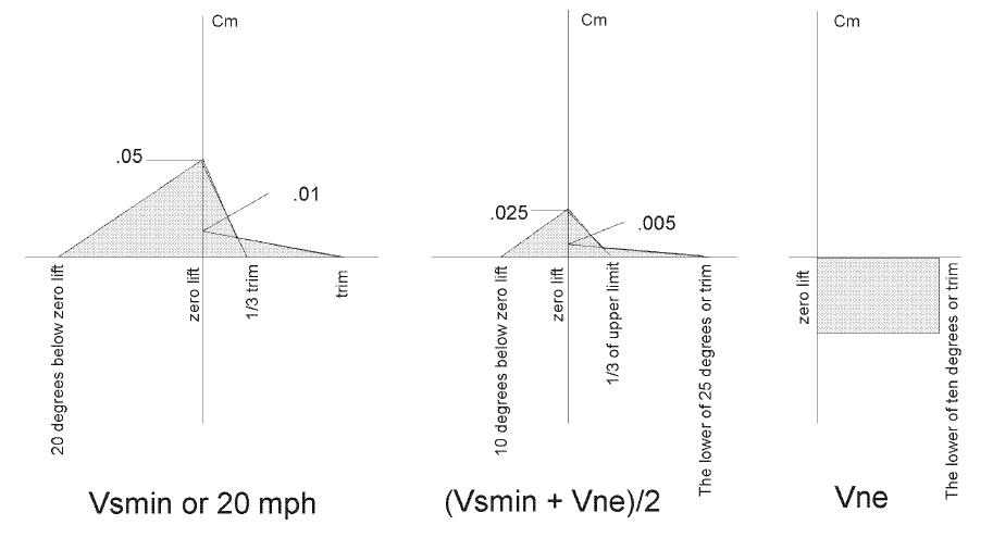 Cm = M / q s c
Cm = pitching moment coefficient (dimensionless)
M = pitching moment about pilot tether point in ft.lbs.
q = dynamic pressure (in slugs/ft-sec2 ) = .5 p v^2
s = projected planform area in feet2
c = mean chord length in feet
p = air density in slugs/ft3 (Standard sea level density is .002377)
v = calibrated airspeed in ft/sec
If the moment origin (point of rotation) is not the pilot tether point, the moment values should be transferred to the tether point using conventional aerodynamic techniques. The raw data, and the actual calculation of Cm, including all values used in the calculation, is required.
For purposes of data correlation, the in-flight trim angle of attack must be compared to the vehicle trim angle of attack. The calculations and methods used must be included in the report. This may be done by comparing in-flight pilot/control bar position at trim with the keel attitude, which produces this position on the ground and then correcting for the estimated L/D at trim. This does not necessarily require that the in-flight and vehicle trim angles be equal, however, a gross discrepancy between the two may be cause for the documentation to be called into question.
Comparative Analysis:
The requirements of the LTF Standards and HGMA standards with regard to longitudinal stability as measured on the ground test vehicle are very similar, but there are a few notable differences.
The HGMA requirements are specified in terms of the pitching moment coefficient, whereas the LTF requirements are specified in terms of the pitching moment. The strength of the pitching moment is a function not only of the level of stability by also of the size of the wing – a larger wing with the same stability will produce a larger moment. The pitching moment coefficient is independent of the size of the wing, and thus provides a more accurate measure of the stability level independent of the wing area. The HGMA requirements are therefore written in a more valid form in this regard.
The HGMA requirements require testing to a lower speed than the LTF requirements, which may be significant for the phenomenon of turbulence induced tumbling, which theory and observation suggest is primarily a low speed phenomenon. The LTF requirements require testing to a higher speed, and have a higher minimum stability requirement at higher speeds, which may be significant with regard to dive recovery or avoidance of uncontrolled high speed dives.
Of the two of these safety concerns, historically, among modern hang gliders, turbulence induced tumbles have been the more significant area of concern, involving the greater number of incidents in which a pilot’s safety was compromised. Overall, there is no evidence from the actual safety record that either of these two testing requirements for vehicle stability tests has provided for a relatively increased level of safety over the other.
3. Adequate Structural Strength
Requirements for adequate structural strength, as determined by tests, are specified in each of the two standards. Tests under the LTF standards are normally performed on a ground test vehicle. Tests under the HGMA standards are always performed on a ground test vehicle.
LTF Standards:
2.3 Structural strength
2.3.1 The hang glider has to withstand following load factors without any structural damages to the material or connections:
a) positive test load: +6g’s
b) negative test load: -3g’s
Notes: The load capacity test has to be performed as a simulation of the load factors occurring in flight. The given mass is the maximum takeoff mass minus half of the gliders mass.
For special cases a static test (sandbag test) can be performed. An elliptic weight loading pattern for positive loads and a rectangular weight loading pattern for negative loads towards the wingtips has to be applied. Towards the chord, the center of the applied load has to be at minimum 35% of chord line no matter if positive or negative loading.
HGMA Standards:
THE FOLLOWING VEHICLE LOAD TESTS SHALL BE CONDUCTED AND DOCUMENTED:
POSITIVE LOAD TEST:
With the root section at +35 degrees angle of attack, or at the stall angle of attack as confirmed by documented tuft testing, or at the angle of maximum resultant force as confirmed by load versus angle of attack data, the minimum required ultimate test speed shall be the greater of:
1) Va/.707
2) Vne / .816c
The minimum required limit load speed shall be:
Min. req. ultimate test speed * .816
NEGATIVE 30 DEGREE LOAD TEST
With the root section at negative 30 degree angle of attack, the minimum ultimate test speed shall be the greater of:
1) Va
2) Vne * .866
The minimum required limit load test speed shall be:
Min. req. ultimate test speed * .816
NEGATIVE 150 DEGREE LOAD TEST
With the root section at a negative 150 degree angle of attack, the minimum required ultimate test speed shall be:
50% of the required minimum ultimate positive test speed, but not less than 30 mph.
The minimum required limit load test speed shall be:
Min. req. ultimate test speed * .816
Comparative Analysis:
It is in the structural requirements that the LTF Standards and HGMA standards differ by the greatest degree from one another, and in this area of airworthiness specification, the HGMA requirements are demonstrably more valid with respect to hang glider structural strength.
The LTF standards specify structural requirements in terms of G loads. This type of specification of structural requirements is quite valid with respect to a conventional aircraft design, such as an airplane, where the wing is relatively inelastic, where loads and load distributions are relatively simple to compute, and where operating speeds make a direct aerodynamic simulation of in-flight loads impractical.
In hang gliders, however, the wing can be very elastic, and this elasticity can vary significantly from one design type (flex wing) to another (rigid wing). Consequently, loads and load distributions are difficult to calculate accurately. At the same time, the relatively low operating speeds of hang gliders make it practical to place the glider on a test vehicle at the same airspeeds and angles of attack that may be seen during maneuvering flight, or indeed at even greater combinations of airspeed and angle of attack, thereby testing the wing directly for structural strength under real world conditions.
For example, let us assume that a hang glider stalls at 30 kph, and we wish it to be able to maneuver safely with full and abrupt application of nose up control, at a speed of up to 60 kph. Calculation will tell us that the load on the glider when flown at 60 kph at the angle of attack that corresponds to one G flight at 30 kph, will be as high as 4 G’s. Applying a standard safety factor of 1.5, we may then derive a required ultimate positive load capacity of 6 G’s.
Another way to write this requirement is to require that we test the glider on the vehicle at its maximum lift angle of attack, at a speed of 60 kph for limit loads, and at a speed of 60 kph multiplied by the square root of 1.5, or 73.4 kph, for ultimate loads.
In the HGMA standards, the required speed for this test is 105 kph. A rigid wing, with no aeroelasticity, that had a stall speed of 35 kph, would need to have an ultimate load capacity of 9 G’s in order to pass the HGMA test. However, this same wing could pass the LTF test with an ultimate load capacity of only 6 G’s, and could achieve that load at a test speed of only 85 kph. At the same time, however, a rigid wing is also likely to have lower total drag values at high speed and therefore be more easily capable of attaining higher speeds in flight – so the structural margin of safety for a rigid wing would be far lower under the LTF testing protocol.
At the same time, a flex wing with an aeroelastic offload factor of 35%, with the same 35 kph stall speed, would develop only 5.85 G’s during this test. If this more flexible wing did not fail during this test, then it would have been proven to have the same real world structural capacity as a 9 G rigid wing – and to have far greater strength than a 6 G rigid wing. Yet, if this flexible wing failed at 5.95 G’s, it would not be able to pass the LTF 6 G requirement.
It can therefore readily be seen that the HGMA test specification is a more valid means for specifying structural airworthiness.
In addition, the HGMA contains an additional structural test – the negative 150 angle of attack test -that is very relevant to the issue of tumbling in turbulence and structural survival of such tumbles, as it simulates the loading condition that a hang glider would experience mid-way through a tumble event, at a point where the wing might still recover to normal flight if it did not suffer a structural failure. The LTF standards contain no structural test specifically related to surviving a tumble or a tail slide. In this sense, the HGMA tests are more rigorous and demanding than the LTF tests.
Overall Conclusions
The LTF and HGMA airworthiness standards are very similar in the manner in which they define and specify airworthiness in a hang glider. Where the standards differ, it can be shown that the differences are either not significant, or that the HGMA standards contain the more valid definition of airworthiness for the modern hang glider.
In addition to the specific definitions of airworthiness that are contained in the two standards, there are differences in the manner in which the standards are administered. The LTF standards are administered by an independent testing authority while the HGMA standards are administered by a manufacturer’s association. Historically, it has been shown that both of these approaches have been successful in producing a high degree of airworthiness in hang gliders that meet these standards. The Federal Aviation Administration of the United States Department of Transportation has officially recognized the validity of the HGMA airworthiness standards, and has, in fact, developed an entirely new program of airworthiness certification for Light S